IMKO HD2 SONO-M1 for Construction Aggregates

A California-based construction materials and contracting company approached us with the challenge of accurately determining moisture content in their range of construction aggregates, including granite, recycled materials, crushed stone, gravel, river rock, and sand. The traditional method of kiln/oven testing was labor-intensive, time-consuming, and often produced inaccurate results.

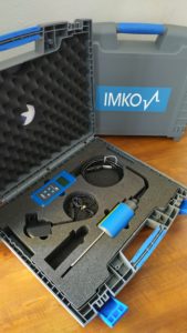
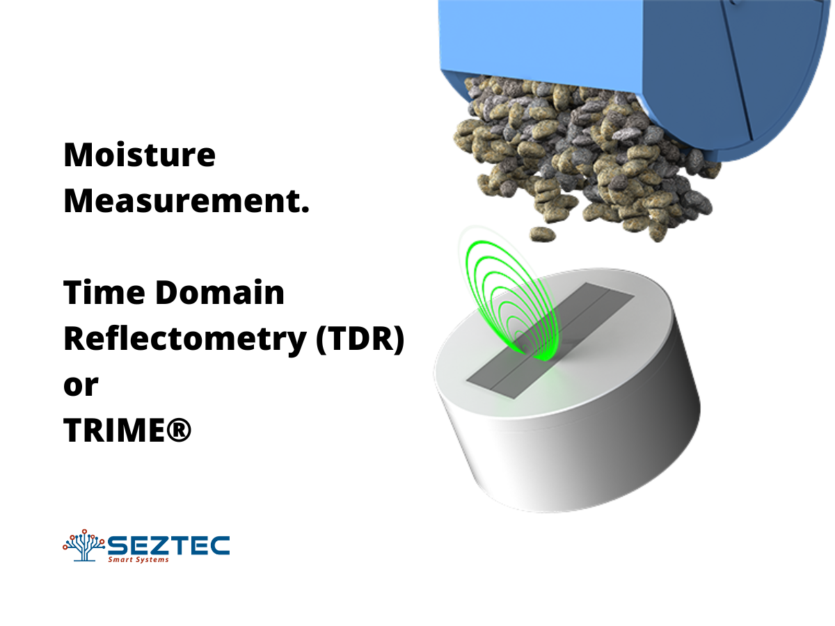
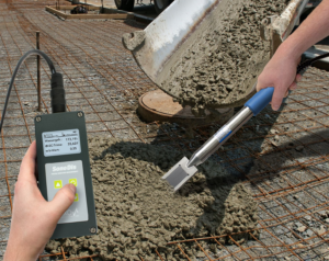
In response, we proposed the use of our IMKO HD2 SONO-M1© Portable Moisture Meter as a solution. The HD2 moisture meter utilizes TRIME (time domain reflectometry) technology, a superior measurement method compared to kiln drying and other technologies such as capacitive moisture sensors. TRIME technology offers faster response times, superior measurement accuracy, and the ability to handle higher conductivities.

We are confident that the IMKO HD2 SONO-M1 will provide the construction company with a fast, accurate, and efficient solution for determining moisture content in construction aggregates.


Portable Moisture Meter


Portable Moisture Meter


The IMKO HD2 SONO-M1 Moisture Meter is suitable for a wide variety of applications, including but not limited to:

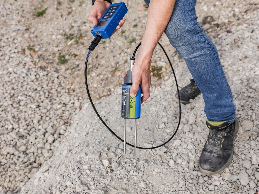
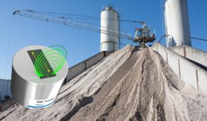
› In-situ moisture measurement of construction aggregates (sand, washed concrete sand, grit, crushed stone, gravel up to 1-1/4″)
› Concrete and asphalt production
› Ready-mix and pre-cast industry
› On-site product testing
› Also suitable for highly conductive materials like Soil, Clay, Foundry Sand, Ore, Slag, and Coal (using SONO M1C probe)


IMKO HD2® is a hand held aggregate moisture meter


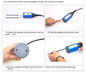
Additionally, the IMKO HD2 Portable Moisture Meter boasts a 100% modular design, allowing for ultimate flexibility and convenience. The sensor probe can be detached from the handheld device for easy replacement or repairs, and even the sensing prongs on the probe are replaceable in the event of damage. This level of versatility is rare among our competitors and ensures that your investment is protected for the long term. With the HD2, you can expect unbeatable results and the industry’s highest accuracy, day after day, for years to come.


Contact us today if you have a similar measurement requirement and we would do our best to work with you!

Moisture Measurement in Soy Beans

Introduction:

In the grain industry, proper storage of grain is essential to avoid spoilage and reduce germination. This becomes even more critical in the case of soybeans, which are more susceptible to spoilage due to their high oil content. It is crucial to maintain proper moisture levels for soybean storage, with commercial soybeans stored at 13% moisture or less for winter storage and soybean seed stored at 12% moisture or less over one planting season.


IMKO grain moisture meter for dryers


Challenge:

Ensuring proper moisture levels in soybeans can be a challenge, as the drying process can easily damage the fragile soybeans if air temperature is too hot or too dry. Additionally, rough handling during the process can also harm the grain.

Solution:

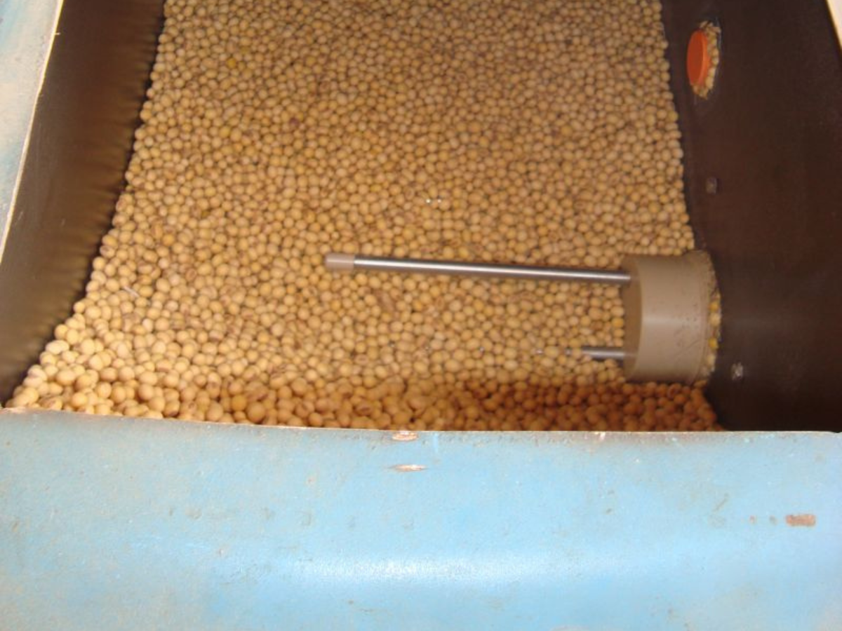
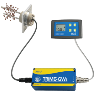
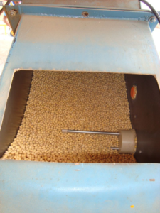
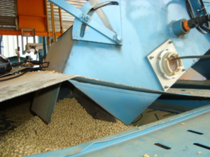
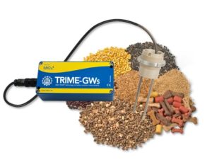
To address this challenge, Seztec offers the TRIME GWs grain moisture probe, a state-of-the-art, radar-based in-line moisture sensor that can be installed in grain conveyors, bins, or dryers. The sensor provides real-time and accurate moisture measurements in soybeans, allowing for precise temperature control during the drying process and ensuring optimal grain health.


soy bean moisture


soy bean moisture


Features:

Versatile: TRIME GWs grain moisture probe is perfect for materials such as soybeans, corn, rice, wheat, cereals, oil seeds, pulses, dried fruit, animal feed or animal fodder, cat food, dog food, woodchips, powders, granulate, and any other type of grain.

Real-time measurement: TRIME GWs sensor provides real-time moisture measurements in soybeans, allowing for precise temperature control during the drying process.

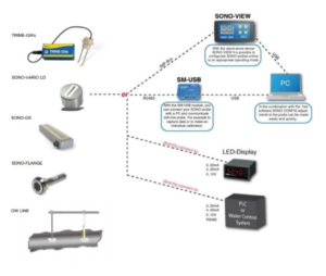
Data transfer: All TRIME probes are offered with a variety of standard industry outputs and communication protocols to meet every data transfer need. The measured parameters such as moisture content, conductivity, and temperature can be transferred directly into a PLC via two analogue outputs 0(4)…20 mA or imported via an RS485 and IMP-Bus interface.

User-friendly: TRIME GWs grain moisture probe can be connected directly to a local PC (USB port) via the SM-USB module or the field display, SONO-VIEW, allowing for easy adjustments and calibrations.


 Grain moisture probe


Conclusion:

TRIME GWs grain moisture probe provides an effective solution for maintaining proper moisture levels in soybeans and ensuring optimal grain health during the storage and delivery process. With its real-time measurement and versatile compatibility, it is a valuable tool for the grain industry.

Do you have a tricky moisture measurement application? Contact us at sales@seztec.com or call us at (816) 204-0808 to explore our complete range of moisture measurement solutions.

Case Study: Ensuring Optimal Grain Health in Soybean Processing with TRIME GWs Grain Moisture Probe 

Published by:
Seztec USA
copyright © 2022 Seztec LLC

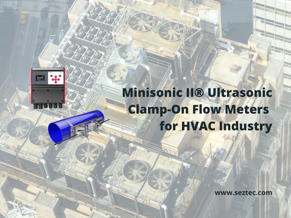
Clamp-On Ultrasonic Flow Meters for HVAC

Seztec’s Minisonic Ultrasonic Clamp-On Flow Meters are the perfect solution for measuring multiple key parameters in heating or cooling HVAC systems! Whether you need to track supply and return water flow, CHW pump flow, or check metering, these flow meters provide accurate results every time. In addition, they are ideal for hydraulic balancing, leak detection, supply and return temperature measurements, and even heating or cooling energy consumption (BTU). So if you want to improve the efficiency and performance of your HVAC system, choose the Minisonic Ultrasonic Clamp-On Flow Meters by Seztec!


Applications of Ultrasonic Clamp-On Flow Meters in HVAC Industry


Experience the versatility and convenience of Minisonic flow meters with both Portable and Fixed options! The Minisonic II Portable offers mobility and on-site measurement capabilities, while the Minisonic Fixed offers a permanent solution for your flow measurement needs. Choose the right option for you and enjoy accurate and reliable flow measurements with Minisonic.
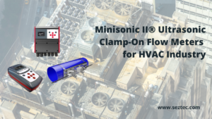
 

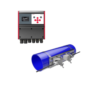
Minisonic Ultrasonic Clamp-On Flow Meter


Minisonic II Fixed Ultrasonic Flow Meter:

The Minisonic II fixed flow meters are a highly efficient solution for measuring heating or cooling energy consumption (BTU) in HVAC systems. These meters are ideal for cost allocation and sub-metering applications. Their versatile design enables them to be deployed in a wide range of applications in HVAC systems, including chiller supply headers, condenser lines, main chilled water headers, supply and return lines for chilled and hot water, boilers, and heat exchangers, with a large diameter range capability up to DN 10,000.


hvac flow meter for chiller water flow

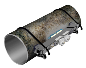
Minisonic II Portable Ultrasonic Flow Meter:

Unlock the full potential of your HVAC system with the Minisonic II Portable Ultrasonic Flow Meters! Whether it’s optimizing pump flow, conducting hydraulic balancing, performing flow surveys, verifying flow meters, or detecting leaks in your CHW or hot water network pipes, these portable flow meters are the ideal solution for all your maintenance needs. Get ready to take your HVAC system to the next level!
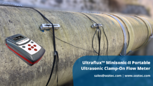
 

portable ultrasonic flow meter


Measuring Principle:

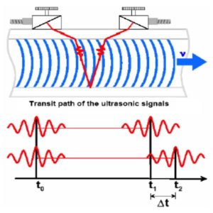
The Minisonic Ultrasonic Flow Meters utilize the transit-time technology, which is based on the principle of time-of-flight, to determine the velocity of fluid flow and the volumetric flow rate. The device comprises two transducers that alternate in emitting and receiving ultrasonic signals. The difference in transit time between the transmitted and received signals is directly proportional to the liquid flow rate and is used to calculate it.


ultrasonic flow meter principle


HVAC Challenges:

The HVAC system in a building is a critical component in ensuring the comfort and safety of its occupants. However, it is prone to several mechanical and hydraulic issues that can cause energy losses and affect the efficiency of the system. The Minisonic II Flow Meter offers a solution to these common HVAC challenges:

(1) Pumping and Insufficient Water Flow Issues

One major inefficiency in a heating or cooling system is related to water flow problems within the system. Over time, pumps can experience internal wear and tear that decreases their overall efficiency and affects their ability to provide the specified water flow (gpm) to the system. Insufficient water flow through the system can cause significant damage to the chillers and can also cause the pipes to freeze. Therefore, monitoring pump flow and chiller flow accurately is critical to the well-being of your HVAC system.

(2) Hydraulic Balancing

Water-cooled chillers reject absorbed heat through an additional water loop, called condenser water lines, which feed heated water to the cooling towers for cooling. A building may have more than one cooling tower to meet its energy demand. To ensure maximum cooling efficiency, the operator must ensure an equal amount of water flows through each cooling tower/cell. The Minisonic II Flow Meter can be installed on the condenser pumps to accurately measure the condenser water flow reaching the cooling towers. This information can help the operator optimize their pump flow for maximum cooling efficiency.

(3) Energy Loss at Low Water Flow Rates

During low-demand times, the building may consume much lower cooling or heating energy. Accurately measuring these low flow rates is crucial as energy transfer at low water flow rates typically goes unmetered, effectively giving away “free energy.” The Minisonic II Flow Meter can measure extremely low flow velocities (0.03 ft/s), ensuring that no energy goes unmetered and providing maximum return on investment to energy producers.

(4) Maintenance Costs

Maintenance costs are a significant operating cost of a heating or cooling system, including pump overhaul, chiller overhaul, insulation costs, flow meter or BTU meter recalibration and replacements, water leaks, water treatment, etc. The Minisonic II Flow Meter is a 100% clamp-on solution and does not require any pipe cutting for installation, removal, or replacement. The flow meter can be retrofitted at any location within your HVAC system and can be moved to a different location in the future without requiring a system shutdown. As the flow sensors are attached externally to the pipe, they do not come into contact with the liquid, ensuring the flow meter will not require maintenance or recalibration throughout its lifespan. Furthermore, the Minisonic II flow meter features permanent ultrasound coupling pads (elastomer pads), replacing the traditional ultrasound gel that can wash away due to pipe condensation on CHW pipes. The permanent coupling pads eliminate the need for periodic flow meter maintenance to reapply ultrasound gel, keeping your maintenance and operating costs low.


HVAC ultrasonic flow meter


(5) Network Water Leaks

Chilled water systems, especially in district energy plants, are connected to a vast network of underground insulated water pipes that stretch for miles. These lines are typically unmetered, and any network leaks go undetected. By retrofitting with the Minisonic II non-intrusive flow meter, operators can monitor supply and return water flows in the main headers and individual branches to detect water leaks, without the need to meter the entire network.

In conclusion, the Minisonic II flow meters are a reliable and efficient solution to meet the challenges faced by HVAC systems. These flow meters provide accurate and non-invasive measurement of liquid flow rate, ensuring maximum efficiency and cost savings. With its large pipe diameter range, the Minisonic II can be installed in various points in the HVAC system, making it a versatile and adaptable solution. Additionally, its maintenance-free and retrofit nature, reduces the overall maintenance costs and downtime of the HVAC system. In short, the Minisonic II flow meters are the ideal choice for building owners, plant operators, and engineers who strive for maximum energy efficiency, cost savings, and hassle-free operation of their HVAC systems.

We offer flow meter rental service so you can carry out pump flow verification, flow meter verification, and hydraulic balancing at your cooling plant. Our rental solutions are 100% non-intrusive, meaning no pipe cutting needed to make measurements.

Here is an interesting case study about hydraulic balancing where we helped a cooling plant optimize their condenser water flow.

Contact us today with your measurement problem!

www.seztec.com | sales@seztec.com

Published by:
Seztec USA
copyright © 2022 Seztec LLC
Published on: May 12, 2022 at 19:01
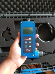
Moisture Measurement with TRIME®

With Seztec’s TRIME® TDR technology you can measure material moisture precisely, directly, non-destructively, and economically in construction aggregates, fresh concrete, grains, soil, and more.


What is TRIME® Radar technology?


Time Domain Reflectometry (TDR) is used to accurately determine moisture content in materials by correlating the speed of propagation of high frequency electromagnetic pulses (1GHz) with the di-electric constant (or relative permittivity) of the material being tested.


grain moisture meter measuring field


TRIME® is a proprietary technology that stands for Time domain Reflectometry with Intelligent Micromodule Elements and is based on the TDR principle or “cable radar”.


TRIME IMKO TDR


The high frequency pulses are generated and guided through the transmission lines or sensing probes (also called as wave guides) into the material. When the pulses are reflected at the probe surface and back to the propagation source, the TDR response time “t” is then evaluated. This TDR response time is directly proportional to the moisture content present in the material. Since water has a significantly higher dielectric constant than the materials to be measured, such as sand, grain or even soil, it is possible to determine the water content with a high degree of accuracy.

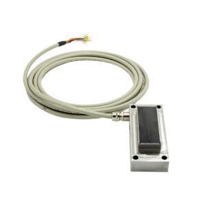
The TRIME® sensors are offered in various configurations to match the target applications and installation locations. For applications in the concrete industry the sensor is offered as a flat sensor head (SONO probes) where the signal conductor is placed between ceramic plates for continuous moisture measurements in a process and to endure high level of surface abrasion. Whereas in grain or soil applications, the sensors have a conventional probe design to allow material penetration for accurate moisture readings.


Why TRIME®?


For a long time due to its complexity and high cost of implementation, TDR technology remained a laboratory measurement system for experimental science and R&D. And measuring devices based on TDR were highly uncommon due to their very large size, making them impractical for field use. In 1980’s, IMKO revolutionized the field of miniaturized TDR technology and developed proprietary TRIME® sensors to be used for measurement of moisture content in a variety of environmental and industrial applications. TRIME® is a robust measurement technology, which enables a compact and industry compatible design with a very good price/performance ratio.


What are Key TRIME® Applications?


All aggregates and bulk solids contain a proportion of water. In addition to the quality of the final product, moisture also determines the weight and the price. Legal requirements lay down the framework. With material moisture measurement, you can determine the water content in your aggregates and bulk solids. Our SONO probes were specifically developed for applications in the construction industry. SONO-VARIO Standard is suitable for general fine bulk solids like Sand and Gravel upto 5/32 inch, whereas the SONO-VARIO Xtrem is designed for highly abrasive materials like Gravel, Grit, Rock, Stone up to 1-1/4 inch.


sand moisture probe


Furthermore, moisture measurement in fresh concrete is another problematic area that our SONO sensors can help solve for concrete production plants such as ready-mix plants. Controlling the moisture content and the temperature of the new concrete can can increase the structural integrity of the concrete and make it more resistant to future cracking. Most important parameters are water content and the W/C-value to reach the desired quality. The SONO-WZ®is an easy and convenient portable measurement system to measure concrete moisture directly on-site in under 10 seconds!


Fresh Concrete Moisture Meter


Whereas, the SONO MIX MINI Fresh Concrete Moisture Meter is designed to be installed directly in concrete mixers (intensive mixers) to provide continuous real-time moisture readings to the operator to ensure consistent concrete batches are produced.


fresh concrete moisture sensor for mixers


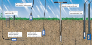
Environment studies and crop production are another key applications for our TRIME sensors. For instance, our sensors are used to measure soil moisture content and electrical conductivity (salinity) for crop producers, farmers, and environmental scientists. When it comes to measuring the soil moisture content, there are various requirements for sensors. In many applications, high-resolution measurements are to be carried out selectively in a very narrow pattern, for example when near-surface water conditions are intended to be investigated for water balance models or to attend evaporation experiments. But also in the laboratory or in the greenhouse, it is often necessary to limit the size of the moisture measuring field, so that undisturbed results are guaranteed. In all these applications, our PICO 32 Soil Probes can demonstrate its assets . Thanks to the various interfaces, the probe can be integrated into many data environments without much effort.


PICO soil moisture probe


Another area of focus is measurement of grain moisture. When grain is harvested, it usually contains excess water. If the grain is stored in a silo, this excess water would cause mold to form immediately, resulting in the total loss of the product. Therefore, all common grain types are dried before being stored in a silo, usually using a vertical dryer with product passing through it once (continuous dryer). The input moisture is measured to determine the water quantity to be removed, and the dwell time or throughput rate is controlled based on the known dryer performance. This not only ensures that the product does not go moldy later in the silo, but also that you are not wasting energy unnecessarily by over-drying the product. The innovative TRIME® GWs grain moisture sensor technology enables accurate, continuous measurements directly in the drying process at temperatures of up to 120°C (248°F) and regardless of the type and composition of the product to be dried, such as cereals, oil fruits and pulses, food, animal fodder, wood chips, powder and granulate.


grain moisture meter for dryers


Do you have a tricky moisture measurement application? Contact us at sales@seztec.com or call us at (816) 287-2035 to explore our complete range of moisture measurement solutions.


Published by:
Seztec USA
copyright © 2022 Seztec LLC

Thermal Mass Flow Meter – Measuring Principle

Thermal mass flow meters are used for direct mass measurement of fluids (gases or liquids) flowing through a pipe. Unlike volumetric flow meters such as turbine, variable area, etc., thermal mass flow meters are not affected by temperature or pressure of the fluid being measured.


How do thermal mass flow meters work?


Thermal mass flow meters are based on King’s Law that introduces the relationship between rate of heat absorption in a flowing medium to its mass flow velocity.

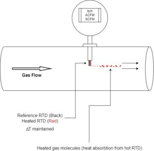
The sensing probe in thermal mass flow meters consists of two temperature sensors (see diagram below), one of which measures the process temperature (Black RTD), and the other is an electrically heated sensor (Red RTD) that disperses heat energy to the flowing fluid molecules through heat convection. A pre-determined temperature difference, ∆T, between both sensors is maintained by the flow computer by constantly supplying electrical voltage to the heated sensor. The rate of flow of fluid is directly proportional to the electrical energy supplied to the heated sensor. The electrical signal is scaled and converted to mass flow signal by the flow computer.


Thermal mass flow meter measuring principle


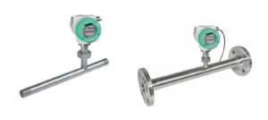
Our thermal mass flow meters are offered in various configurations including insertion and in-line – see below.


Thermal mass flow meter types


Insertion flow probes are suitable for applications where pipe cutting or installing flanges is not desired or forbidden. Therefore, a process connection is made in the pipe via hot tapping or cold tapping to install proper connection fittings for the insertion flow probe.

The second meter type is the flanged with in-line flow body and is suitable for new installations where process shutdown is possible. The operating principles, construction, and applications of both flow meter configurations are identical. Whereas the factors that will affect the performance of these meters is the process conditions, installation conditions, and meter sizing.


Advantages of thermal mass flow meters:


› Measurement of mass flow, direct output of standard volume flow, without additional measurement of pressure and temperature
› No moving parts, therefore low maintenance
› Highly accurate than volumetric flow meters
› Low pressure loss due to minor obstruction to flow
› ATEX or DVGW certification available, thus recommended for gases such as natural gas, hydrogen, biogas, etc.
› Highly accurate at small as well as large flow rates
› Pressure and temperature compensated by the thermal mass flow principle
› Easy installation and removal of the sensor from the measuring section


Not sure which flow meter is right for your specific application? Then contact us today and we will be happy to help you find the right instrument for your measuring task. 

CFM vs SCFM in Gas Flow

When designing your flow station for gas flow measurements, the most common confusion begins with CFM, SCFM, and ACFM. All three have similar definitions, but relay totally different data. Let us explain how.


Defining ACFM, SCFM Gas Flow Concepts


CFM stands for Cubic Feet per Minute and is normally used to indicate the working capacity of a pump, compressor, or a blower.

ACFM stands for Actual Cubic Feet per Minute and is a unit of volumetric flow rate of a gas displaced by a pump at operating or present conditions of temperature and pressure.

Whereas SCFM is also a unit of volumetric flow rate that stands for Standard Cubic Feet per Minute. SCFM is the measured gas flow with respect to fixed reference operating conditions and is the most useful measure of gas flow. These reference conditions may vary based on industry and geographical region, but commonly used reference conditions are:

(1) Temperature @ 68°F

(2) Pressure @ 14.5 PSIA

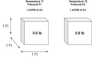
The reason experts around the world introduced the concept of measuring gas flow in SCFM is to standardize all gas flow measurements. This is because, the volume a gas occupies is dependent on its temperature and pressure. For example, a fixed mass of air will occupy larger volume at higher temperature and will undergo compression (smaller volume) at higher pressures.

This means person “A” measuring 1 ACFM of air at their operating temperature T1 and pressure P1 is not the same “amount” or “mass” of air as person “B” measuring 1 ACFM of air at a completely different set of operating conditions (temperature T2 and pressure P2).


Standard vs normal gas flow


Therefore, when gas readings are obtained in SCFM or “fixed” reference conditions, gas flow measurements will be standardized or remain consistent and will mean the same regardless of the operating conditions.


How to obtain gas measurements in SCFM?


To obtain gas flow readings in SCFM, firstly, the gas is measured in ACFM at actual and “known” operating conditions. Meaning a continuous temperature and pressure input is required to track actual operating conditions. The flow computer then uses the below mathematic correction factor, or a variation thereof, to convert ACFM to SCFM that utilizes the actual and reference temperature and pressure values:


convert CFM to SCFM


Ts: Standard Temperature

Ps: Standard Pressure

Ta: Actual Temperature

Pa: Actual Pressure


If you would like to speak to an expert about your gas flow application then contact us at sales@seztec.com

Explore our range of gas flow meters


Copyright © 2022 Seztec LLC

Flow Measurement on Asbestos Cement Pipe

A successful case of flow measurement on asbestos cement pipe using Ultraflux Uf801P non-contact water flow meter.

As early as the 1930’s, asbestos cement (AC) pipe had been widely used by cities and municipalities to transport domestic water to households and commercial buildings all around the United States. It was used because of its light weight, low coefficient of friction, and resistance to corrosion. After discovery of associated health risks with asbestos in drinking water, new installation of AC pipes has long been ended, but thousands of miles of existing AC water pipes are still beneath our streets that have never been replaced. These pipe networks still need to be monitored for water consumption and water leaks and municipalities have long relied on in-line/flanged water meters for this purpose. AC Pipes have significantly higher break rates since these pipes are nearing their life cycle; therefore, they cause undetected underground leaks resulting in hefty water loss annually.


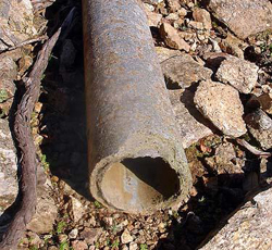
 image credit: www.osha.oregon.gov
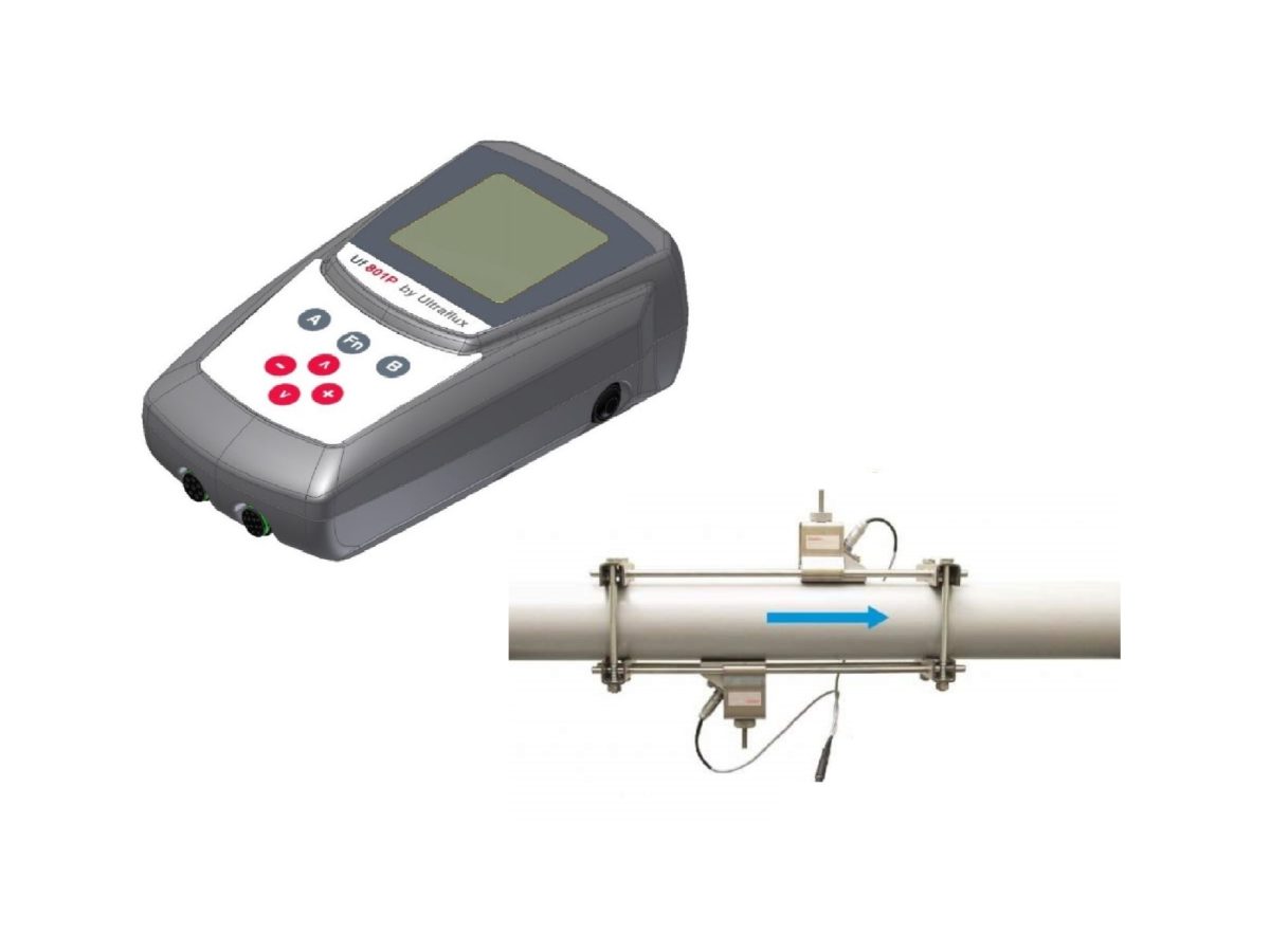
 

Because of the deterioration seen in AC pipes, it can become very tricky to install new water flow meters in the water network as pipe cutting can cause leaks or serious pipe damage that can cost thousands of dollars in repairs. To avoid this problem we offer our “non-contact ultrasonic flow meters” to accurately monitor water consumption, and detect leaks in real-time without cutting into the pipes.


ultrasonic flow meter


data center energy consumption flow meter


Our non-contact ultrasonic flow meters are mounted externally on the AC pipe and require no mechanical works like pipe cutting, flange installation, and drilling. Thus ensuring that pipe integrity is conserved and losses are minimized.

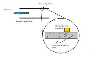
One major problem with measuring water flow on AC pipes is the deterioration of the pipe walls that causes air and water pores within the pipe walls that interfere with signal transmission of a non-contact ultrasonic water flow meter. Therefore, specialized sensors with enough signal penetration power are needed to make successful non-contact measurements on these “porous” pipes. Not all non-contact water flow meters in the market are capable of being successful on AC pipes. Seztec is one of the very few industry leaders that offers custom sensors with extremely low frequencies (high penetration power) that make flow measurement even on AC pipes possible.


asbestos cement pipe


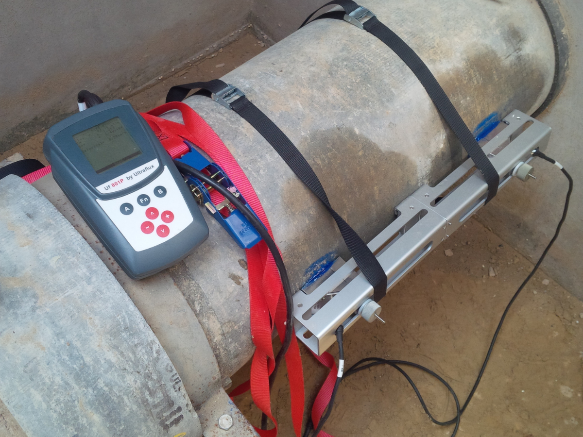
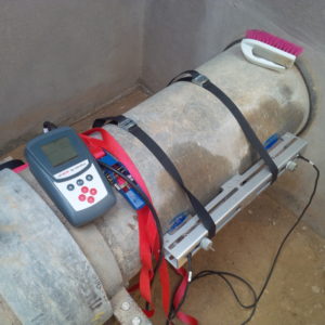
Below is a great example of a successful water flow test using our Uf801P non-contact water flow meter (portable flow meter) on a DN300 asbestos cement pipe. We used an ultra-low frequency sensor to achieve stable and accurate flow measurements on several underground pipes for a water district in the US. The measured flow readings were cross-referenced with an existing in-line electromagnetic flow meter and results were within ±0.08%. Our clamp-on ultrasonic sensors are capable of measuring flow on a wide range of pipe diameters (1/2″ to 400″) which makes this instrument a very practical portable tool for all your water monitoring and leak detection needs.

The grease stains as seen below on the pipe indicate that other brands conducted field tests on this location as well, but non of their ultrasonic sensors had enough penetrating power to transmit ultrasound signal through the porous wall and back to achieve usable flow data.


non contact water flow meter


We offer permanent as well as portable non-contact ultrasonic water flow meters. Please contact us with your flow application and our engineers will be very happy to work with you to find a solution!


Originally published Jan 8, 2021 5:30:00 PM, updated April 01 2022

Copyright © 2022 Seztec LLC


Related Products:

Clamp-on Ultrasonic Flow Meter – Ultraflux Uf 801P

Ultrasonic Flow Meter – Ultraflux Uf 811


Clamp-On Ultrasonic Flow Meter or a Mag Meter?

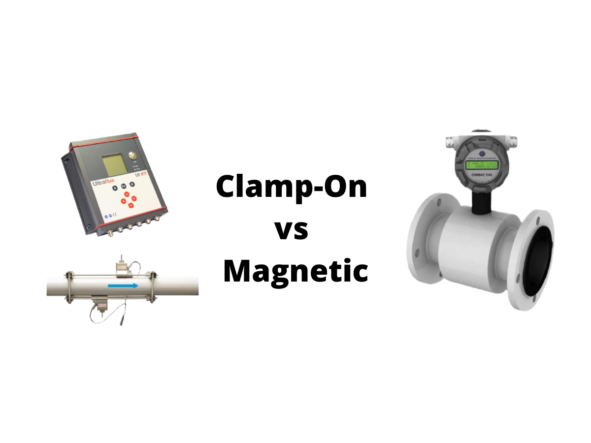
Should you buy an Ultrasonic Clamp-On Flowmeter or a Magnetic Flowmeter? Well, the answer is not that straight forward. When it comes to selecting metering equipment for your process you cannot follow “one size fits all” approach. Meter selection requires a little bit of technical analysis and objective thinking, so having deep understanding about your application requirements will come in handy and help you arrive at the right answer quickly. An incorrect metering instrument for your liquid or gas application can mean thousands of dollars of annual losses resulting from process/plant inefficiency, incorrect flow data, and replacement costs.


clamp on ultrasonic flow meter


To get started, first lets take a quick look at the measuring principles of both metering technologies to get a better hold on the basics.

Ultrasonic Measuring Principle:

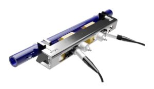
The ultrasonic clamp-on flow meter utilizes transit-time ultrasonic technology (time of flight) to calculate the flow velocity and volumetric flow rate of the liquid. The flow meter consists of two transducers or trans-receivers that alternately send and receive ultrasonic signals to measure the transit time difference between the transmitted and received ultrasound signal. This difference in transit time is a direct measure of liquid flow rate.


ultrasonic flow meter principle


Key benefits of ultrasonic technology:

› 100% non-contact flow measurement (no liquid contact)
› Zero pressure drop created
› No moving parts and no wear and tear of flow transducers – long service life (+10 years)
› No re-calibration required – zero measurement drift
› No risk of pipe leaks – sensors installed externally on the pipe
› Suitable for a wide pipe size range – adaptable to future plant upgrades or pipe replacements
› Modular design – easy sensor and transmitter replacement requiring no system shutdown
› Low installation costs and ownership costs compared to in-line meters
› Accurate and repeatable: normally ±1..3% (±0.5..1% possible with advanced calibration)
› Easy installation and virtually zero maintenance costs
› Can measure conductive or non-conductive liquids
› Independent of liquid temperature, pressure, chemical properties, and viscosity.

Limitations of ultrasonic flow meters:

› Transit-time technology is affected by concentration levels of suspended solids and aeration in the liquid (maximum allowable concentration 5%…10%). Will require a doppler technology to measure liquids with fluctuating or higher solid contents (+10%).
› Not suitable for process control such as batching or chemical injection (slow response time as compared to mechanical meters i.e. turbine or gear meter)
› Highly affected by pipe condition (internal or external pipe rust, uneven surface etc.)
› Not as accurate as in-line meters such as magnetic, Coriolis or turbine meters: normally ±1..3% standard accuracy (±0.5..1% accuracy possible with advanced calibration at extra cost)
› Accuracy highly affected by incorrect pipe dimensions programmed into the meter

Electromagnetic Measuring Principle:

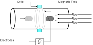
The operating principle of electro-magnetic flow meters is based on Faraday’s Law of Magnetic Induction. This means when an electrically conductive liquid (water-based liquids) flows through the magnetic flux created by the magnetic coils of the flow meter, a voltage is induced across the two electrodes. This induced voltage can be mathematically correlated to the flow velocity of the fluid. The voltage signal is carried to the transmitter to obtain accurate liquid flow readings.


magnetic flow meter principle


Key benefits of electromagnetic technology:

› Much higher accuracy than clamp-on ultrasonic flow meters (±0.1..0.5%)
› Suitable for process control as well as process monitoring applications
› Reliable and field tested technology around the world
› Negligible pressure drop created
› Wide variety of electrode and liner materials to suit a wide variety of applications
› No moving wetted parts – no wear and tear
› Unaffected by suspended solids in the liquid

Limitations of magnetic flow meters:

› Can measure only conductive liquids (5-20μS or higher, e.g. water-based liquids)
› Sensor electrodes prone to internal deposit formation – causes measurement drift in the long run
› Liner materials prone to wear and tear after extended use
› High installation and replacement costs
› Requires proper grounding as flow signals are affected by electrical noise.
› Not as accurate at low-flow velocities.
› Accuracy affected by liquid aeration
› Complicated installation and commissioning procedures

Conclusion:

Every flow measurement application requires proper meter selection to avoid meter failures and process inefficiencies. When designing a measurement station it is important to understand the product to be measured, install the correct equipment, and implement the appropriate correction calculations or factors. The following considerations need to be addressed to minimize measurement uncertainty and monetary losses: What is the composition or fluid to be measured? What is the minimum, maximum and normal operating conditions? How does the operating pressure and temperature affect the fluid? What other operational factors affect proper measurement? Based on the answers to the previous questions, what is the best measuring device to handle the product?

Continue reading “Clamp-On Ultrasonic Flow Meter or a Mag Meter?”

Top 5 Applications of a Clamp-on Flow Meter

Clamp-on Ultrasonic Flow Meters utilize transit-time ultrasonic technology (time-of-flight) to calculate the flow velocity and volumetric flow rate. The flow meter consists of two transducers that alternately send and receive ultrasonic signals to measure the transit time difference between the transmitted and received ultrasound signal. This difference in transit time is a direct measure of liquid flow rate. Learn more here. 


Clamp-on Ultrasonic Flow Meter


Clamp-on Ultrasonic Flow Meter


5 Applications of Clamp-on Ultrasonic Flow Meter:-

Plant managers and maintenance technicians find our Clamp-on Ultrasonic Flow Meters to be very user-friendly because anyone can use our products without requiring deep technical knowledge.  You may carry out various maintenance activities using our portable flow meter (Uf801P or Minisonic II) such as:

1. HVAC Commissioning (water side): All HVAC systems (heating and cooling systems) require several checks during the commissioning stage before the final hand-over. Our portable Clamp-on Ultrasonic Flow Meters can help with primary and secondary pump output flow verification (GPM), network leak detection, bypass-valve control check, hydraulic balancing, and much more.

2. Flowmeter Verification: In-line flow meters such as turbine or electromagnetic flowmeters suffer from calibration drift over time due to several factors. This drift causes tremendous measurement errors, which affects the efficiency of your process or quality of the final product. Our Uf801P or Minisonic II Clamp-on Ultrasonic Flow Meter can be installed adjacent to your existing flowmeters for a quick accuracy check. This will help you ensure whether or not your flow meters are performing as per specified accuracy.

3. Energy Audits:  Our portable Clamp-on Ultrasonic Flow Meters are equipped with two temperature inputs to measure supply and return temperatures in a heating or cooling system. The flow meters are supplied with a set of (optional) matched clamp-on temperature sensors, just like the flow transducers, to avoid pipe cutting. The flow meters provide energy consumption (BTU or kWh) using the temperature and flow measurements. Our Clamp-on Ultrasonic Flow Meter is a great tool for ESCO’s (energy service companies) to perform energy audits to create an energy model of any facility.

4. Leak Detection: Our Uf801P portable clamp-on ultrasonic flowmeter is also an ideal solution for water leak detection in network pipes. For instance, this Clamp-on Ultrasonic Flow Meter can sense liquid velocities down to ±0.03 ft/s so even small movement in water at low-peak times can be precisely detected.

5. Network Metering: Water utility companies and district cooling plants have an extensive water pipe network (underground and above ground). During the design phase a lot of these pipelines are not provided with critical metering points that are required for proper measurement and control of the infrastructure. The Uf801P or Minisonic II Clamp-on Ultrasonic Flow Meter can help operators carry out temporary flow measurements at various points in the network to study the feasibility of adding additional metering points.


We offer clamp-on ultrasonic flow meters for permanent monitoring as well as for temporary measurements. Contact us today at sales@seztec.com with your flow measurement application!


Originally published Feb 20, 2022 3:30:00 PM

Copyright © 2022 Seztec LLC


Related Products:

Clamp-on Ultrasonic Flow Meter – Ultraflux Uf 801P

Portable Flow Meter – Ultraflux Minisonic II

Ultrasonic Flow Meter – Ultraflux Uf 811


Non-contact water flow test on a 51″ pipe

The customer wanted to perform a water flow survey on a 1.5 mile long mains water pipeline at 5 different locations to ensure that there was no water leakage and that the flowrate was as per the design to meet the local demand.


Ultraflux uf801P portable ultrasonic clamp on flow meter rental


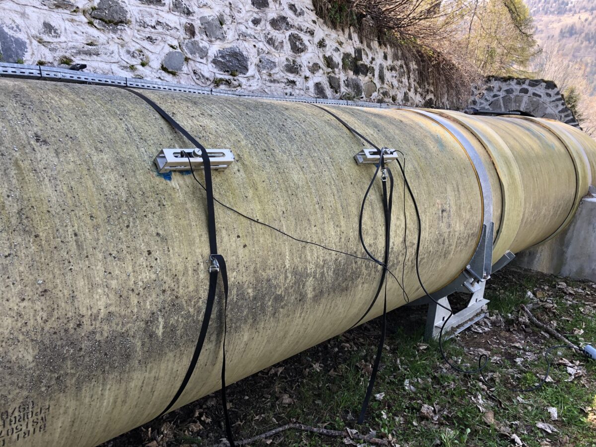
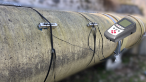
This turned out to be a successful non-invasive water flow test on a 51″ (1,300mm) GRP pipeline using our UF801 Portable Clamp-on Flow Meter without any pipe cutting or drilling.


We successfully performed this water flow survey using our clamp-on flow metering technology without any alterations to the pipe line or system shutdown. Customer needed an average accuracy of +/-5% but our equipment exceeded the expectations and delivered an average accuracy of +/-2%. Needless to say, it was possible to further enhance the accuracy of the readings up to +/- 0.5 – 1% on such large pipe diameter by utilizing two flow channels on our UF801 flowmeter. By doing so, it would be possible to average flow velocities along to different planes across the pipe’s cross-section to achieve a more stable and accurate flow reading.